Adjust the PV module layout
After Outline and Roof direction, the Module layout step shows a proposed module arrangement on the surface. It estimates the number of panels and installable capacity based on your installation assumptions.
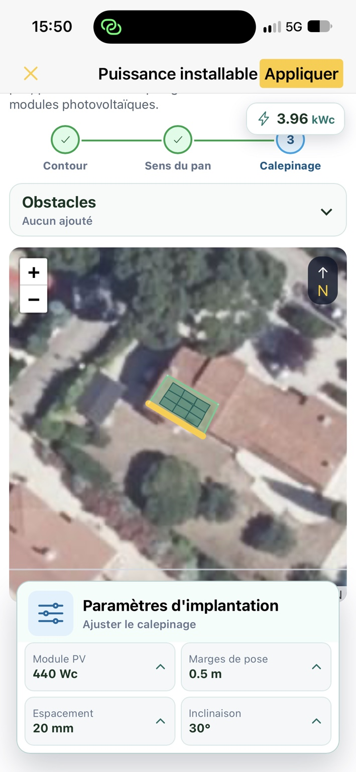
Review the proposed layout
Section titled “Review the proposed layout”The map shows the roof outline and proposed panel positions. The Installable capacity badge, in kWp, updates according to the modules placed. This is not instantaneous electrical power: it is the total rated peak capacity of the modules in the layout.
Check that panels remain within the relevant area and that their arrangement matches the surface direction and known constraints.
Change the layout settings
Section titled “Change the layout settings”Open Layout settings and adjust the relevant sections:
| Setting | Effect on the result |
|---|---|
| PV module | Select the model or format, dimensions and rated capacity in Wp. |
| Installation margins | Distance between the panel array and the surface edges; uniform or per-side settings, depending on the controls shown. |
| Spacing | Gaps between modules; uniform or separate horizontal and vertical settings. |
| Tilt | Surface tilt used for the layout. |
The arrangement and estimated capacity update when you change the settings. Depending on the available options, you can change module orientation (portrait/landscape) or optimize their arrangement. Maximizing panel count does not remove the need to check actual site constraints.
Add roof obstacles
Section titled “Add roof obstacles”The Obstacles section lets you add and edit areas to exclude or work around. Available types include Roof window, Chimney and Other obstacle (ventilation outlet, rooflight, antenna, etc.).
- Open Obstacles.
- Add the corresponding feature or a custom obstacle.
- Position it on the map and adjust its dimensions, rotation and clearance where these settings are available.
- Check that the revised layout avoids this area.
Keep the distinction clear: roof obstacles used for physical module placement are different from horizon obstacles used for shading analysis. The two functions serve different purposes.
Apply the layout
Section titled “Apply the layout”- Check the displayed modules, installable capacity and any obstacles.
- Tap Apply in the Installable capacity tool.
- Return to the assessment settings and check the capacity and orientation summary.
- Tap Apply in the analysis settings to recalculate the assessment if needed.
Points to check
Section titled “Points to check”- Accuracy depends on the map outline, module dimensions and selected setbacks.
- The layout is a preliminary assessment estimate. It does not replace an installation drawing or technical approval of the installation.
- If you later change capacity manually, check which value is actually used in the production calculation.
Related articles
Section titled “Related articles”- Determine installable capacity
- Outline the surface
- Set the surface direction
- Configure the PV system
Resume a layout from the web portal
Section titled “Resume a layout from the web portal”If the project contains a layout created or edited in the web portal’s layout editor, the mobile tool displays a message identifying the web portal layout. The placement is retained in the project. To change its modules or obstacles, open the Azimutis web portal layout editor; the mobile editing steps described here do not apply to this placement.
Projects with several planes
Section titled “Projects with several planes”In a multi-plane project, select the plane before editing its sizing, orientation, layout or height. Editing a shared survey affects every plane using it. Consumption, battery and economic assumptions remain common to the installation.